Light Meter Replacement
Time is the greatest killer of all vintage cameras. The electronics in them tend to be exposed to the elements to some degree, either directly or through the unsealed nature of these early electronic-enabled cameras. If someone accidentally leaves the batteries in for a long period of disuse, they can leak and cause corrosion in the battery compartment, before eventually spreading into the rest of the camera. Other natural processes will also eat away at the solder joints and exposed wires strewn about the inside of these older cameras over time.
In my case, the solder joints on the light meter's main circuit board were showing signs of damage, and extracting the board necessitated replacing it a non-existent replacement, thus began the mini-project of cloning, redesigning, and manufacturing a replacing it with a board of my own make.
Doing some basic probing with a multimeter, I determined that I'd need a trimmer potentiometer in the range of a few kiloohms, finally selecting the 20kOhm TC33X-2-203G as my trim-pot of choice. A single thin film resistor was necessary to replace the printed resistive wire as well.
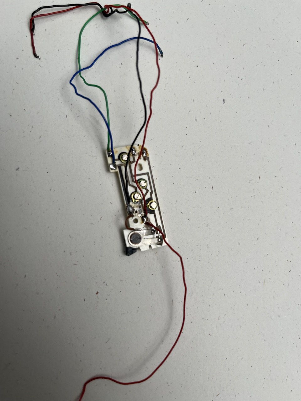
The original light meter circuit board extracted from the camera.
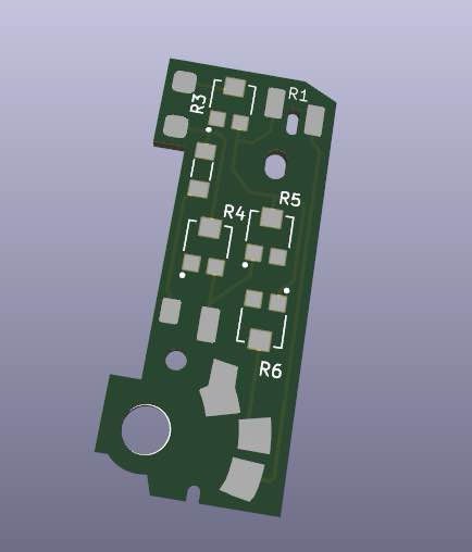
Copy and redesign of the board in KiCad
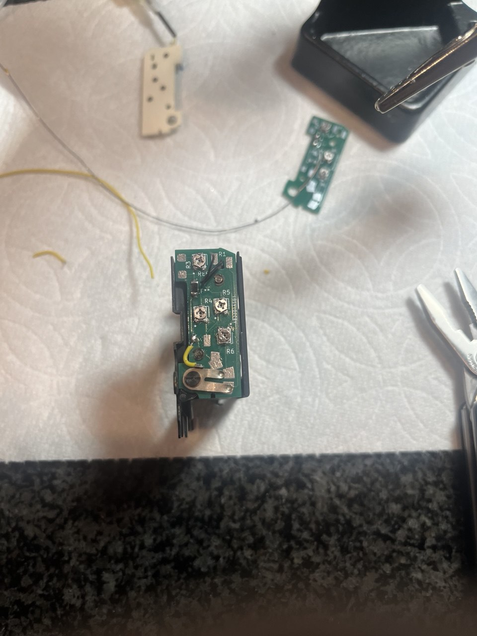
Installing the new replacement board in the camera.
v2?
One issue with my replacement was that I stuck too closely to the limitations of the original design, using only one side of the pcb. This led to the trim-pots being offset from their original positions, making them hard to calibrate once installed in the camera. If there is somehow demand or I end up doing more of these repairs, it might be worth redesigning the pcb slightly to be more faithful to the original. Until that day though, v1 does the job and that's all I need at the moment.