FilmFrame
But Why?
I thought it would be cool to have a new way to display one's film photographs. What I didn't anticipate was just how much effort it would be to design said new way to display them.
The FilmFrame is a physical display for medium format slide film with a remote controlled variable-brightness backlight. Having tinkered with an Arduino and an STM32 board on a test project before this one, I selected the Raspberry Pi Pico 2 and the RP2350 chip as my platform of choice.
The Concept
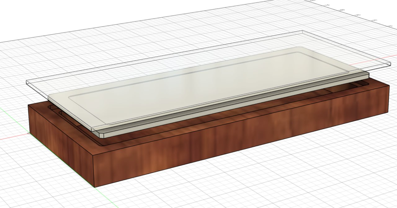
Inspired by the classic minimalist picture frame, I wanted something similar to display slide film, either hung on a wall or sitting on a shelf, that controllable via a remote for convenience and in order to simplify the physical design.
Using PWM for brightness control was my first instinct, however, using a buck converter that had an output voltage configurable via PMBus was an interesting prospect and something I wanted to try for this project. I selected the Vishay MicroBuck SIC451ED-T1-GE3 as my buck converter of choice to design around for this project.
My remote of choice was the Apple TV Remote, being one that physically looked pretty nice, had some online information about its protocol, and was readily available in both genuine and knock-off form. This was paired with a TSOP4838 IR receiver.
The Code
Shockingly, this was one of the easier parts of the project. Raspberry Pi provides a whole toolkit for developing on the Pico 2/RP2350 platform, and the process of learning how to program the Pico 2 was a pretty enjoyable one as well with made things even easier to work through.
This part of the process involved implementing a few key features:
- The PMBus protocol
- Power control for the MicroBuck
- Input handling for the IR Remote
PMBus
The PMBus protocol is an extension of the I2C protocol for communicating with other ICs on a circuit board, with a few extensions to make it more useful in a power management context. Using the builtin I2C peripheral on the RP2350, I wrote some helper functions to abstract away the complexity of issuing PMBus commands over I2C.
/*
...
Other functions for reading and writing single-byte, word, and no-data commands via PMBus.
...
*/
int PMWriteWord(i2c_inst_t *i2c, uint8_t addr, uint8_t cmnd, uint16_t word) {

    // A byte array of the command, the low byte of the word, and the high byte of the word
    uint8_t commandData[3] = {cmnd, word & 0xFF, (word >> 8) & 0xFF};

    int wroteCommand = i2c_write_blocking(i2c, addr, (uint8_t*) &commandData, 3, false);
    if (wroteCommand == PICO_ERROR_GENERIC || wroteCommand != 3)  {
        return -1;
    }
    return 0;
}
Apple Remote
PIO
In order to read the incoming IR signal from the receiver, leveraging the PIO on the RP2350 became a necessity to keep up with the incoming data without blocking the main processor and wasting cpu time. After spending a few days reading through the PIO documentation and getting an idea of how it worked for myself, I adapted and slightly modified someone else's PIO assembly for handling IR input in favor of writing my own from scratch. Thank you mcuapplab for having already solved this problem.
; Modified Apple-semi-compliant NEC IR reciever on a 10us clock period state machine
;
; Based on a samsung reciever by mcuapplab
; https://mcuapplab.blogspot.com/2022/11/raspberry-pi-pico-pioprogrammable-io_15.html

.program ir_rx
start:
mov isr, NULL
set x, 31                   ; Counter to get 9ms (32 * 28 * 10us = 8960)
start_pulse:
jmp pin start
jmp x--, start_pulse [26]

; TODO: Repeat pulse detection by duplicating the following around the expected
; repeat pulse signal but with shorter durations.

wait 1 pin 0
set x, 31
mov isr, NULL               ; Clear the ISR before we start evaluating the start gap.
start_gap:
in pins, 1
mov y, isr
jmp !y  start               ; There might be a reliability optimization by repeating the
jmp pin start_gap [10]      ; in-mov-jmp code block to replace 9 of the delay cycles here.

mov isr, NULL

set x, 31
bit_loop:
wait 1 pin 0
nop [31]
nop [31]
in pins, 1
wait 0 pin 0
jmp x--, bit_loop
push
irq 0

wait 1 pin 0
wait_stop:
jmp pin, wait_stop

wait 0 irq 0
Wikipedia Lies
My original source for the Apple TV Remote's protocol was the wikipedia article about the remote, which towards the end described the protocol for handling it (screenshot of the version of the Wikipedia page I first encountered below).
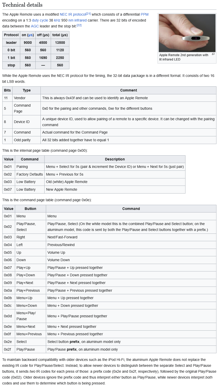
However whenever I was testing the PIO output and what I was reading from the remote, I would get what was seemingly nonsense that didn't come close to matching what the Wikipedia page implied I should be seeing.
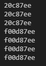
This discrepency had frustrated me to the point that I started using my oscilloscope so I could physically look at the IR receiver's output and count the bits in it for myself.
Further experimentation using a genuine and a knockoff remote eventually showed that only a few bits of the received signal were changing, which would be expected if each remote was identical sans a different ID number, so the PIO program was doing something right and the remotes weren't faulty.
While re-reading the Wikipedia article, I noticed that the commands it claimed were correct were uncited and didn't have a source, so I began going through the edit history of the article to find the point at which a source I could follow might appear.
I soon found out that someone, all the way back in 2015, had edited the wikipedia page to delete all of the correct information that had sources cited, and replaced it with uncited fabrications. Even worse, source [22] in the screenshot above had information in it that directly conflicted with the fake information that this person had inserted. Going all the way back to 2012 yielded the first version of the page that contained correct information: https://en.wikipedia.org/w/index.php?title=Apple_Remote&oldid=503748456
With the correct information in hand, I could stop trying to figure out why my remotes didn't work and focus on handling the commands I was now receiving.
top-half/bottom-half
While writing the code to handle the remote control commands, I ended up naturally implementing my own version of the top-half/bottom-half architecture for handling interrupts.
// Main program loop
while (1)
{

    if (!queue_is_empty(&command_queue)) {
        uint8_t command;
        if (queue_try_remove(&command_queue, &command)){
            switch (command)
            {
            case APL_CENTER:
                last_command = APL_CENTER;
                ff_toggle(BUCK1EN);
                break;
            case APL_UP:
                last_command = APL_UP;
                ff_brightness(true);
                break;
            case APL_DOWN:
                last_command = APL_DOWN;
                    ff_brightness(false);
                break;

            // Do nothing on an unrecognized command.
            default:
                break;
            }
        }

    }
}
I believe this should actually be a
[while(queue has items)]loop rather than only checking once per main program loop, but its highly unlikely for the user to manage to input more than a single command in the time this takes to run so I figured there's no practical difference in changing my implementation
With all that said and done, we now have a program that can control the brightness of our LED array via communicating to the buck converter over PMBus.
The Design
LED Array
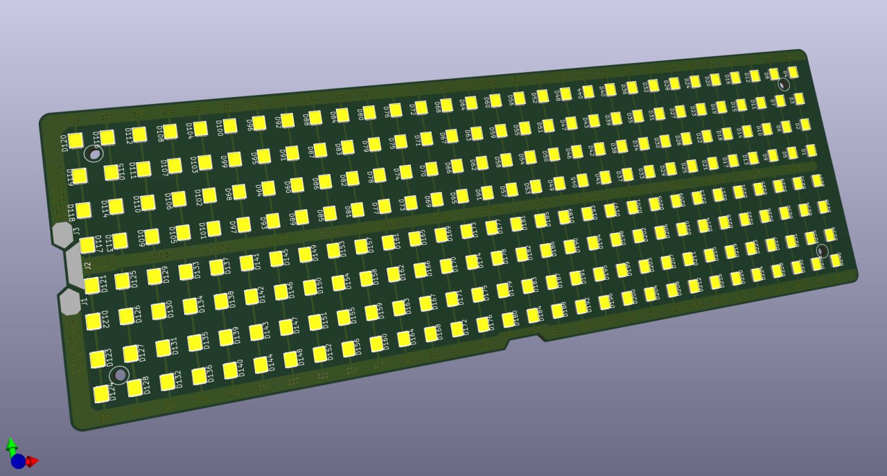
This was by far the easiest part to design; all I had to do was copy-paste the LEDs 240 times and wire them up.
Control Board
This board would contain the USB-C PD circuit, the power control circuitry for brightness control, and the RPi Pico 2 and IR receiver for power management and input processing.
The first order of business was copying the evaluation board's schematic into KiCad so I could do component selection and begin designing the physical board for everything to sit on.
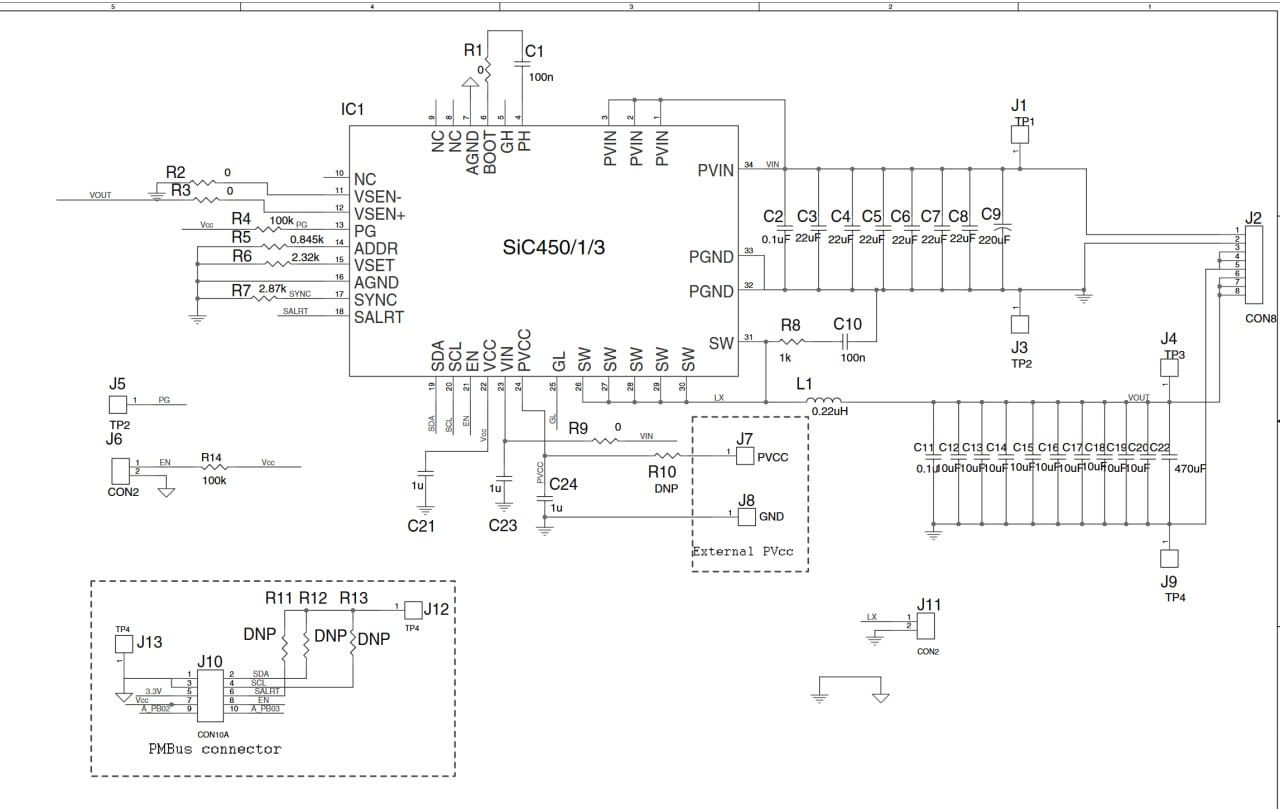
Eval board schematic
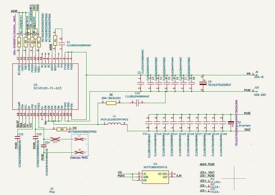
Eval board schematic transcribed into KiCad
The process of designing the rest of the circuits was just me copying down what I'd done on my breadboard into KiCad
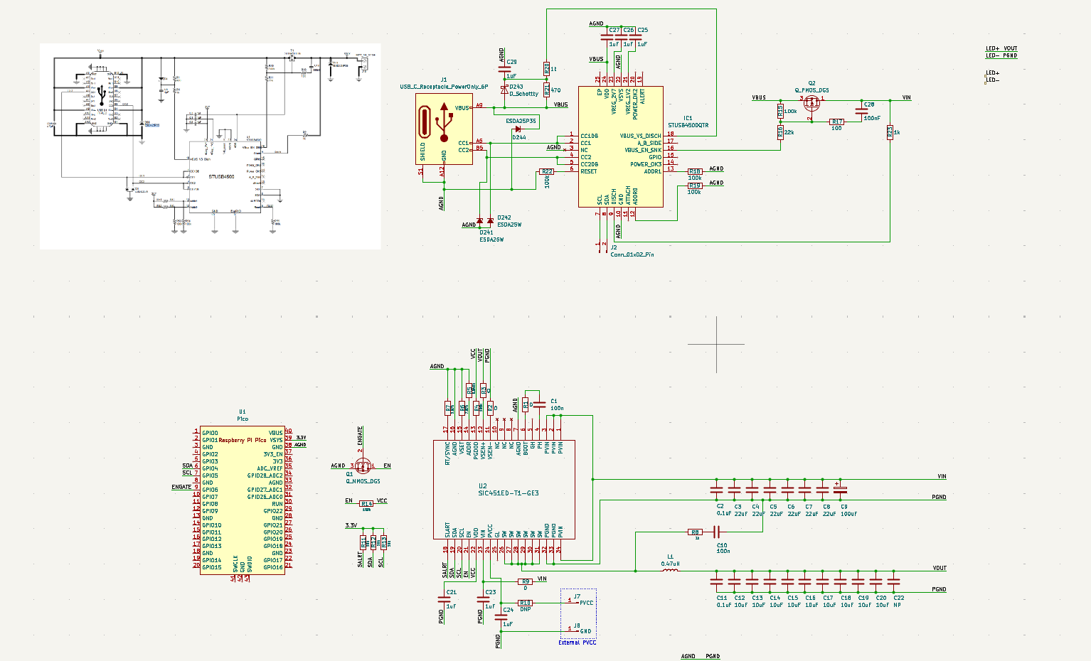
An early draft of the schematic, missing the IR receiver, and with the USB PD circuitry I would soon remove.
I made the decision here to use the entirety of the Pico 2 instead of directly implementing it on my own board for two reasons:
When I first selected the Pico 2 as my platform of choice, the RP2350 didn't have general availability yet, so I couldn't have designed around it even if I wanted to.
Using the Pico 2 as a mezzanine board simplifies my design greatly, and eliminates the chance that I might incorrectly implement the RP2350 and its requisite circuitry myself.
USBPD
My initial plan for upstream power delivery was implementing my own on-board usb-c controller to negotiate for the power I'd need, but I quickly figured that it would be far easier to buy pre-made boards and simply configure them to output my desired power. At this point in the project, I did not want to spend the time programming to control another chip and add another point of failure to my design.
As a result, I selected the Adafruit HUSB238 as my USB C PD breakout board of choice. My solution was to do a cutout on the control board where the Adafruit board would sit in place of doing my own PD circuitry.
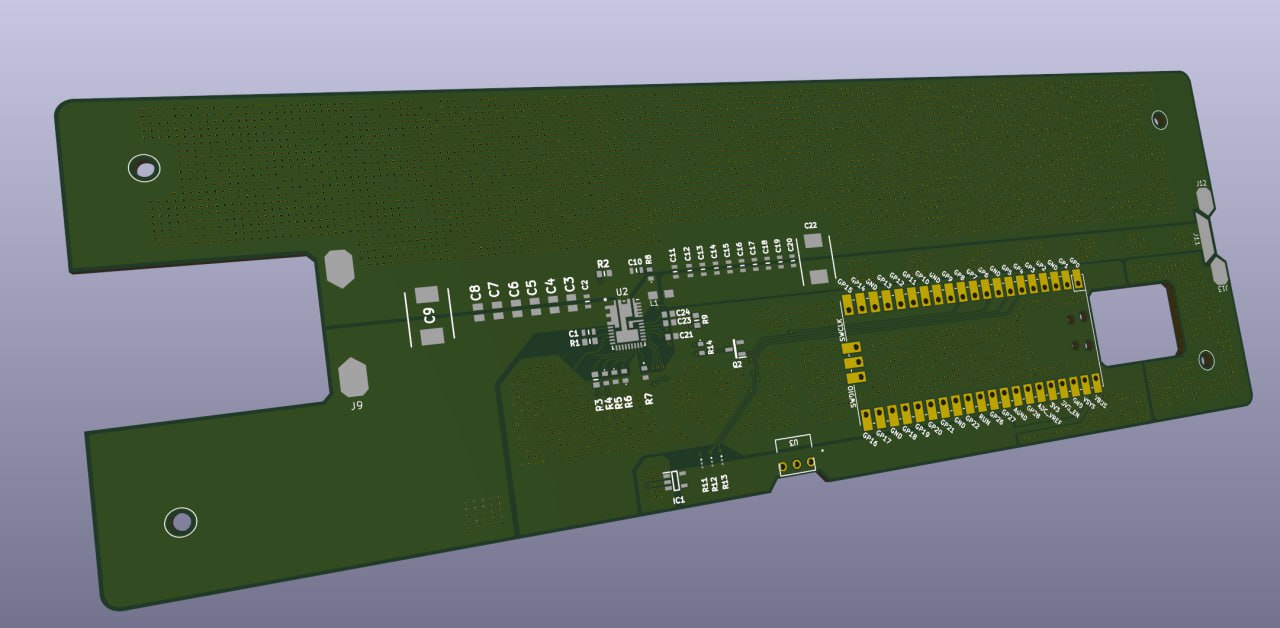
The cutout for the Adafruit board on the left.
Full prototype of the boards
Issues with the power delivery
Loosely assembling the LED array and Control boards together, they worked initially at first, however a fatal issue soon arose. I made an error in my component selection in the inductor for the buck converter, having picked one that's datasheet seemed to match the requirements, but in reality was insufficient. Running the buck converter would lead to severe overheating in the inductor to the point that it would desolder itself from the board.
The end, for now...
Sadly, after getting two different large PCBs manufactured and purchasing the requisite components to populate them, my budget for the project ran out after this point, and it was difficult to justify spending more time and money on it as classes loomed ahead.